


What Are Welding Defects? A Complete Guide
Welding defects are a major concern in metal fabrication and manufacturing, affecting structural integrity, safety, and performance. Understanding the causes, types, and prevention methods of welding defects is crucial for ensuring high-quality welds.
Concept of Welding Discontinuities and Defects
In the ISO 6520 welding standard, which focuses on fusion welding processes, different types of welding discontinuities and weld defects are classified. Recognizing these issues helps in maintaining quality control and preventing structural failures.
What Is a Discontinuity in Welding?
A welding discontinuity refers to any irregularity in a welded joint that disrupts the integrity of the weld. Not all discontinuities affect the function of the welded component, but they can still indicate potential issues in the welding process.
What Is a Defect in Welding?
A weld defect is any discontinuity that either:
- Compromises the functionality of the welded component.
- Exceeds the acceptable limits defined by welding standards such as ISO 6520 or AWS D1.1.
Thus, every welding defect is a discontinuity, but not every discontinuity is classified as a defect. A discontinuity becomes a defect when its size, type, or distribution surpasses standard acceptance criteria, making the weld unacceptable for use.
According to the ISO6520 welding standard, welding defects are categorized into six groups, which we will examine in detail:
What Are the Different Types of Welding Defects?
The ISO 6520 welding standard classifies welding defects into six major categories. Each defect type has unique characteristics and can impact weld quality in different ways. Below, we examine common welding defects, their causes, and preventive measures to improve weld performance.
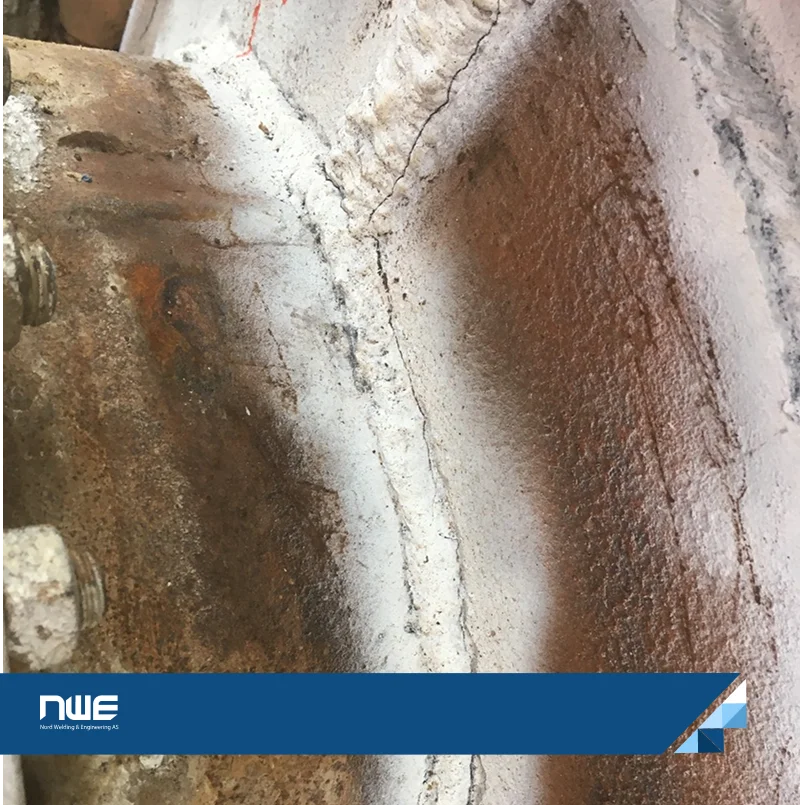
Welding Cracks: The Most Dangerous Defect
Cracks are one of the most severe welding discontinuities, as they can lead to complete failure of the welded joint. Cracks occur due to localized tearing caused by thermal, residual or applied stresses during welding and cooling. These defects can appear in both the weld metal and base metal, significantly reducing weld strength.
Types of Cracks in Welding
According to ISO 6520 welding standards, welding cracks are classified into two main categories:
- Hot Cracks (Solidification Cracks): These form during the solidification phase of the weld metal due to shrinkage stresses.
- Cold Cracks (Hydrogen Cracks): These develop after solidification, often due to hydrogen embrittlement or residual stresses.
Additionally, cracks are categorized based on their appearance:
- Micro Cracks: Tiny cracks visible only under a microscope.
- Longitudinal Cracks: Cracks that run parallel to the weld axis, commonly seen in submerged arc welding.
- Transverse Cracks: Cracks perpendicular to the weld axis, typically caused by excessive compressive stresses.
- Radial Cracks: Cracks radiating outward from a central point.
- Crater Cracks: Small cracks at the end of a weld pass, often due to improper arc termination.
- Group of Disconnected Cracks: A cluster of small cracks in the weld metal.
- Branching Cracks: Multiple connected cracks originating from a single point.
Causes of Cracks in Welding
Several factors contribute to the formation of welding cracks, including:
- Improper Preheating and Post-heating: Failure to maintain the correct preheat or interpass temperature increases the risk of cracking.
- Use of Moist or Inappropriate Electrodes: Leads to hydrogen embrittlement, causing cold cracks in welding.
- Poor Joint Design: Excessive penetration-to-width ratio can create stress concentrations that result in cracking.
- Welding Under High Restraint Conditions: Prevents the weld from expanding and contracting naturally, leading to cracking.
- Rapid Cooling After Welding: Causes internal stresses that promote crack formation.
- Impurities in the Base Metal: Elements like sulfur and phosphorus weaken the weld, increasing the likelihood of cracking.
How to Prevent Welding Cracks?
To reduce the risk of cracks in welding, follow these best practices:
✔️ Preheat and post-heat the metal according to welding procedure specifications (WPS).
✔️ Use low-hydrogen electrodes and store them in a dry environment.
✔️ Optimize joint design to minimize excessive stress concentrations.
✔️ Control cooling rates to avoid rapid temperature changes.
✔️ Ensure proper welding technique to prevent crater cracks at the end of a weld pass.
By understanding welding crack types, their causes, and effective prevention methods, welders can improve weld quality and reduce the chances of structural failure.
In the next section, we will explore other common welding defects, including Cavities, lack of fusion, and incomplete penetration.
Cavities in Welding: Causes, Types, and Prevention
Cavities are a common type of welding defect caused by trapped gas during solidification. These defects can weaken the weld by creating voids that compromise its structural integrity. Understanding the types of cavities in welding, their causes, and how to prevent porosity in welding is essential for achieving high-quality welds.

What Are Cavities in Welding?
Cavities are hollow spaces or voids that form within the weld metal due to gas entrapment during solidification. These imperfections are typically spherical but can also appear as elongated voids. In some materials, such as cast iron welds, gas cavities may form in layers, affecting weld durability.
While weld porosity is less dangerous than sharp discontinuities like cracks, excessive porosity indicates poor welding technique, contaminated materials, or incompatibility between base and filler metals. Proper control of welding parameters is crucial to prevent these defects.
Types of Cavities in Welding
Different types of gas cavities and shrinkage cavities can form during the welding process, each with distinct characteristics:
1. Gas Cavity (Gas Pore)
A gas cavity forms when gas becomes trapped in the weld metal during solidification. It appears as a small, round void within the weld bead.
2. Porosity in Welding
Porosity refers to small, spherical gas cavities dispersed within the weld metal. It is one of the most common weld defects caused by trapped gas.
3. Uniformly Distributed Porosity
This occurs when gas cavities are evenly spread throughout the weld, creating a consistent but weak structure.
4. Clustered or Localized Porosity
When gas pores group together in one area, they form clustered porosity, which can significantly reduce weld strength.
5. Linear Porosity
This defect consists of aligned gas cavities that run parallel to the weld axis. It often results from poor gas shielding or contamination.
6. Elongated Cavity
Unlike standard porosity, elongated cavities are non-spherical voids that form due to gas entrapment in a specific direction.
7. Wormhole (Worm Tracking Porosity)
A wormhole is a tubular gas cavity formed when gas escapes through the solidifying weld. This type of porosity often occurs in flux-cored arc welding (FCAW).
8. Surface Pore
A surface pore is a visible gas cavity that breaks through the weld surface, making it easy to detect during visual inspection.
9. Surface Porosity
This refers to multiple surface-breaking gas cavities, often caused by poor shielding gas flow or contamination.
10. Shrinkage Cavity
A shrinkage cavity forms due to solidification shrinkage, leaving a void in the weld. It occurs when the molten metal does not fill the joint completely.
11. Interdendritic Shrinkage
This type of shrinkage cavity develops between dendrites during solidification, affecting the weld’s microstructure.
12. Crater Pipe
A crater pipe is a shrinkage cavity found at the end of a weld pass, often due to improper arc termination.
13. End Crater Pipe
An end crater pipe is an open shrinkage cavity that reduces the weld cross-section, weakening the final joint.
How to Prevent Cavities and Porosity in Welding?
To minimize gas-related welding defects, follow these best practices:
✔️ Use proper shielding gas flow to protect the weld pool from atmospheric contamination.
✔️ Keep electrodes and filler materials dry to prevent moisture-related porosity.
✔️ Ensure proper surface preparation by removing oil, rust, and other contaminants before welding.
✔️ Optimize welding parameters such as voltage, travel speed, and arc length to reduce gas entrapment.
✔️ Control cooling rates to prevent shrinkage cavities and crater cracks at the weld’s end.
✔️ Use appropriate welding techniques, such as back-stepping or crater filling, to eliminate crater pipes.
By understanding the different types of cavities in welding and implementing effective porosity prevention techniques, welders can significantly improve weld quality and ensure long-lasting, defect-free joints.
In the next section, we will explore Solid Inclusions which can compromise weld strength and reliability.
Solid Inclusions in Welding: Causes, Types, and Prevention
Solid inclusions are a common welding defect where non-metallic particles become trapped within the weld metal or at the weld interface. These inclusions can weaken the weld structure, reducing mechanical strength and increasing the risk of failure. Understanding the types of solid inclusions in welding, their causes, and how to prevent slag inclusions is essential for producing high-quality welds.
What Are Solid Inclusions in Welding?
Solid inclusions occur when foreign materials, such as slag, oxides, or metallic particles, become embedded in the weld metal. This defect is commonly caused by improper welding techniques, poor joint access, or incomplete slag removal between weld passes.
Unlike gas cavities or porosity, which result from trapped gases, solid inclusions are physical impurities that disrupt the weld continuity. These inclusions can create stress points within the weld, making it more susceptible to cracking or failure under load.
Types of Solid Inclusions in Welding
Solid inclusions can vary based on the type of foreign material trapped in the weld. Here are the most common types:
1. Solid Inclusion
A general term for any foreign material trapped inside the weld metal, leading to weak spots and potential weld discontinuities.
2. Flux Inclusion
Flux inclusions occur when residues from welding flux remain trapped in the weld joint. This defect is common in processes like Shielded Metal Arc Welding (SMAW) and Flux-Cored Arc Welding (FCAW), where flux-coated electrodes or flux-cored wires are used.
3. Oxide Inclusion
Oxide inclusions are caused by metallic oxide particles that form due to poor shielding gas coverage or improper cleaning between passes. These inclusions are common in stainless steel welding and aluminum welding, where oxides form rapidly at high temperatures.
4. Metallic Inclusion
Metallic inclusions occur when foreign metal particles, such as tungsten (from TIG welding electrodes) or copper (from contact tips), become trapped in the weld. These defects can significantly alter the weld’s mechanical properties, leading to potential failure under stress.
Causes of Solid Inclusions in Welding
Several factors contribute to welding inclusions, including:
- Incomplete Slag Removal: Failing to clean slag between weld passes causes inclusions to be embedded in subsequent layers.
- Poor Welding Techniques: Incorrect welding angles, travel speed, or amperage can lead to trapped foreign materials.
- Inadequate Joint Preparation: Rust, scale, or oxide layers on the base metal can result in oxide inclusions.
- Improper Shielding Gas Coverage: In TIG and MIG welding, poor gas flow allows oxidation and contamination.
- Use of Contaminated Electrodes or Filler Metals: Moist or dirty welding consumables introduce unwanted particles into the weld.
- Excessive Arc Length: A long arc length in TIG welding increases the risk of tungsten inclusions due to electrode contamination.
How to Prevent Solid Inclusions in Welding?
To minimize the risk of slag inclusions, oxide inclusions, and metallic inclusions, follow these best practices:
✔️ Clean the weld joint thoroughly before welding to remove oxides, rust, and contaminants.
✔️ Use the correct welding technique, ensuring proper electrode angles and travel speed.
✔️ Remove slag completely between weld passes using a wire brush, chipping hammer, or grinding.
✔️ Ensure proper shielding gas coverage to prevent oxidation and contamination.
✔️ Use high-quality electrodes and filler metals to avoid introducing unwanted materials into the weld.
✔️ Control arc length in TIG welding to prevent tungsten inclusions.
✔️ Optimize welding parameters to avoid excessive spatter and material buildup.
By understanding the types of solid inclusions in welding, their causes, and effective prevention techniques, welders can significantly improve weld quality and structural reliability.
In the next section, we’ll explore lack of fusion defects in welding, another critical issue that impacts weld strength and performance. Stay tuned to learn how to identify, prevent, and address this common welding challenge!
Lack of Fusion and Lack of Penetration in Welding
Lack of fusion (LOF) and lack of penetration (LOP) are two critical welding defects that directly impact weld strength, durability, and structural integrity. These defects occur when the weld metal fails to properly bond with the base metal or when the weld does not fully penetrate the joint, leading to weak welds that may fail under stress.
Understanding the causes of lack of fusion in welding, its different forms, and how to prevent lack of penetration defects is essential for ensuring high-quality welds in any welding process.
What Is Lack of Fusion in Welding?
Lack of fusion (LOF) occurs when the weld metal does not properly bond with the base metal or between weld passes. This defect results in a weak, non-uniform weld with poor mechanical properties. It is often caused by improper heat input, incorrect welding technique, or surface contamination.
Types of Lack of Fusion in Welding
- Sidewall Lack of Fusion: The weld metal fails to fuse properly with the sidewalls of the joint, creating a weak bond.
- Interpass Lack of Fusion: A lack of bonding between two layers of weld metal in multi-pass welding, leading to internal weaknesses.
- Root Lack of Fusion: The weld metal does not fuse with the root of the joint, leaving an unbonded gap that reduces weld strength.
What Is Lack of Penetration in Welding?
Lack of penetration (LOP) occurs when the weld metal does not fully penetrate the root of the joint, leaving a gap in the center of the weld. This defect is particularly dangerous in load-bearing structures, as it significantly reduces the weld’s ability to withstand stress and fatigue.

Types of Lack of Penetration in Welding
- Incomplete Root Fusion: The weld metal does not reach the root face, causing an internal gap in the joint.
- Shallow Penetration: The weld only penetrates a small portion of the base metal, making it weak and prone to failure.
- Irregular Penetration: Uneven penetration occurs due to fluctuations in heat input, leading to inconsistent weld quality.
Causes of Lack of Fusion and Lack of Penetration in Welding
Several factors contribute to LOF and LOP defects, including:
- Insufficient Heat Input: A low heat setting prevents the weld metal from fully melting and fusing with the base metal.
- Improper Electrode Angle: Incorrect torch or electrode positioning can cause incomplete fusion along the joint.
- Fast Travel Speed: Moving too quickly can prevent proper heat penetration, leading to a weak weld bead.
- Contaminated Base Metal: Dirt, rust, grease, or mill scale can act as a barrier, preventing full fusion.
- Excessive Root Gap or Tight Fit-Up: A large root gap may cause incomplete penetration, while a tight fit-up can prevent weld metal from flowing into the root.
- Incorrect Welding Parameters: A mismatch between amperage, voltage, and welding speed can result in weak fusion.
- Incorrect Filler Metal Selection: Using an incompatible filler metal can reduce bonding efficiency.
How to Prevent Lack of Fusion and Lack of Penetration in Welding?
To avoid these critical defects, follow these best practices for proper fusion and penetration:
✔️ Increase heat input to ensure the base metal and weld metal reach full fusion.
✔️ Use the correct welding technique, adjusting travel speed and electrode angle for optimal penetration.
✔️ Clean the base metal thoroughly before welding to remove rust, oil, and contaminants.
✔️ Select the proper filler metal to ensure compatibility with the base material.
✔️ Optimize joint preparation by maintaining an appropriate root gap and bevel angle.
✔️ Adjust welding parameters (voltage, amperage, and travel speed) based on material thickness and welding process.
✔️ Use multiple passes when welding thick sections to ensure full penetration.
✔️ Ensure proper shielding gas coverage in MIG and TIG welding to prevent oxidation.
By implementing these preventive measures, welders can significantly reduce lack of fusion and penetration defects, resulting in stronger, more durable welds.
In the next section, we will examine distortion and deformation in welding, another critical issue that affects weld quality and structural stability.
Welding Shape and Dimensional Defects: Causes, Types, and Prevention
Welding shape and dimensional defects occur when the external shape of the weld deviates from the required specifications, affecting both appearance and structural integrity. These imperfections result from incorrect welding parameters, poor technique, or improper joint preparation.
Understanding the types of welding shape defects, their causes, and how to prevent weld dimensional defects is crucial for achieving high-quality, defect-free welds.
What Are Shape and Dimensional Defects in Welding?
Shape and dimensional defects refer to irregularities in the weld profile, which can compromise the mechanical strength, fatigue resistance, and overall performance of the welded joint. These defects may create stress concentration points, increasing the risk of failure under load.
Types of Shape and Dimensional Defects in Welding
- Undercut in Welding:
-
- A groove along the weld edges that weakens the joint.
- Caused by high travel speed, excessive heat input, or incorrect electrode angle.
- Prevention: Reduce travel speed, maintain proper electrode angle, and use correct amperage.
- Excess Weld Metal (Overwelding):
-
- Occurs when too much filler metal is deposited, resulting in an oversized weld bead.
- Increases material usage and may lead to stress concentration.
- Prevention: Control filler deposition, use proper travel speed and heat input.
- Excessive Convexity in Fillet Welds:
-
- An overly convex weld face that reduces effective throat thickness.
- Caused by low heat input or improper electrode manipulation.
- Prevention: Maintain correct heat settings and adjust electrode movement for uniform bead shape.
- Excessive Root Penetration:
-
- Occurs when the weld metal penetrates too deeply into the root of the joint.
- Can cause burn-through or stress concentration at the root.
- Prevention: Control heat input, maintain proper root gap, and use correct welding speed.
- Overlap in Welding:
-
- Happens when weld metal flows over the base metal without fusion.
- Common in low heat settings or improper welding techniques.
- Prevention: Ensure adequate heat input and correct electrode angle for proper fusion.
- Linear Misalignment (Poor Fit-Up):
-
- Occurs when welded parts are not properly aligned, leading to weak joints.
- Can result from poor joint preparation or incorrect clamping.
- Prevention: Proper fixture setup, tack welding, and alignment checks before welding.
- Sagging in Welds:
-
- Weld metal sinks due to gravity, often in overhead or vertical welding.
- Caused by excessive heat input or incorrect welding position.
- Prevention: Adjust heat input, use proper welding technique, and reduce deposition rate.
- Burn-Through in Welding:
-
- Hole formation in the weld due to excessive heat concentration.
- Weakens the structure and may require costly repairs.
- Prevention: Use proper amperage, maintain optimal travel speed, and control arc length.
- Incompletely Filled Groove:
-
- Occurs when the weld groove is not fully filled, leaving voids.
- Often caused by low deposition rate, insufficient filler metal, or improper joint preparation.
- Prevention: Ensure proper filler deposition, adjust travel speed, and use multi-pass welding if necessary.
- Irregular Weld Width:
- Inconsistent weld bead width, affecting weld aesthetics and mechanical strength.
- Caused by unstable hand movement, incorrect travel speed, or voltage fluctuations.
- Prevention: Maintain a steady hand, consistent travel speed, and proper arc length
11. Root Concavity (Suck Back):
- Shrinkage at the root of the weld, reducing weld throat thickness.
- Can lead to stress concentration and fatigue failure.
- Prevention: Maintain proper root gap, controlled heat input, and optimized gas flow rate.
12. Poor Restart in Welding:
- Irregularities at the point where the arc is restarted, creating weak spots.
- Caused by improper arc striking technique or inadequate cleaning of the previous weld pass.
- Prevention: Ensure smooth arc initiation, clean restart areas, and use a proper restart technique.
Causes of Welding Shape and Dimensional Defects
Several factors contribute to these defects, including:
✔ Incorrect welding parameters: Improper voltage, amperage, and travel speed.
✔ Poor electrode manipulation: Inconsistent movement affects weld bead shape.
✔ Improper joint preparation: Poor fit-up or incorrect root gap.
✔ Excessive heat input: Leads to burn-through, sagging, and excessive penetration.
✔ Lack of operator skill: Unsteady hand movement causes inconsistent weld profiles.
✔ Contaminated base metal: Dirt, rust, or oil can disrupt fusion and bead consistency.
How to Prevent Shape and Dimensional Defects in Welding?
To achieve high-quality, defect-free welds, follow these best practices:
🔹 Optimize welding parameters (voltage, amperage, and travel speed).
🔹 Use proper joint preparation (clean surfaces, correct root gap, and proper fit-up).
🔹 Control heat input to prevent excessive penetration and burn-through.
🔹 Ensure correct electrode angle and movement for even bead deposition.
🔹 Maintain steady travel speed to achieve consistent weld width and shape.
🔹 Perform multi-pass welding when needed for complete groove filling.
🔹 Check welds visually and through testing to identify and correct issues early.
By implementing these techniques, welders can prevent welding shape defects and dimensional irregularities, ensuring a strong, durable, and aesthetically acceptable weld.
In the next section, we will explore welding distortion and deformation, another crucial factor affecting weld quality and performance.
Miscellaneous Welding Imperfections: Causes, Types, and Prevention
In addition to the major categories of welding defects, some miscellaneous imperfections can occur during the welding process. These defects do not fit into the traditional classifications but still affect weld quality, appearance, and performance. Understanding these imperfections, their causes, and how to prevent them is crucial for ensuring high-quality, defect-free welds.
What Are Miscellaneous Welding Imperfections?
Miscellaneous welding imperfections are defects that do not fall under cracks, cavities, inclusions, fusion issues, or shape defects but still impact the integrity of the welded joint. These imperfections can be caused by operator error, poor welding conditions, or external factors such as contamination and electrical instability.
Types of Miscellaneous Welding Imperfections
1. Arc Strikes in Welding
Arc strikes happen when the electrode accidentally touches the workpiece, causing localized melting and surface damage. This leaves behind small craters or hardened spots that can create stress points and weaken the metal.
Causes:
- Accidental contact between the electrode and base metal.
- Poor control of welding equipment.
- Improper handling of the electrode.
Prevention:
- Keep the electrode away from non-welding areas.
- Use proper arc striking techniques to avoid unnecessary contact.
- Maintain control over welding equipment to prevent accidental electrode touches.
2. Weld Spatter
Weld spatter consists of small metal droplets that stick to the surface around the weld, creating a rough, uneven appearance. While it doesn’t necessarily weaken the weld, excessive spatter can affect aesthetics, efficiency, and require extra cleaning.
Causes:
- Excessive voltage or amperage.
- Incorrect arc length or unstable arc.
- Poor-quality electrodes or shielding gas issues.
- Inadequate shielding gas flow, leading to arc instability.
Prevention:
- Adjust welding settings (voltage, amperage, and arc length) for a stable arc.
- Use anti-spatter sprays to prevent metal from sticking to the surface.
- Ensure proper shielding gas flow and use high-quality electrodes.
- Maintain steady hand movements to avoid erratic welding.
Additional Welding Imperfections
Along with arc strikes and spatter, other minor defects may occur, including:
🔹 Electrode Sticking: The electrode fuses to the base metal, disrupting the weld.
🔹 Stray Arc Marks: Accidental sparks that cause minor surface damage.
🔹 Weld Discoloration: Oxidation due to excessive heat or improper gas shielding.
Causes of Miscellaneous Welding Defects
These imperfections often result from poor operator technique, incorrect settings, or environmental factors such as contaminants and electrical instability. Some common causes include:
✔ Improper electrode handling or accidental electrode contact.
✔ High voltage or amperage, leading to increased spatter.
✔ Poor gas shielding, causing oxidation and discoloration.
✔ Lack of skill or control over welding equipment.
✔ Dirty or contaminated base metal.
How to Prevent Miscellaneous Welding Defects?
To avoid these imperfections and achieve clean, professional welds, follow these best practices:
✅ Use correct welding parameters (voltage, amperage, and arc length).
✅ Ensure proper electrode control to prevent accidental arc strikes.
✅ Clean the base metal before welding to avoid contamination.
✅ Use high-quality shielding gas and correct flow rates.
✅ Apply anti-spatter spray to minimize post-weld cleanup.
✅ Maintain a steady arc and consistent welding technique.
By implementing these welding best practices, welders can eliminate unnecessary imperfections and enhance the overall weld quality.
Acceptance Limits for Welding Defects: How Much is Acceptable?
The acceptance criteria for welding defects vary depending on the application, industry standards, and quality classification of the weld. Structural, aerospace, and pressure vessel welding require stricter defect tolerance than general fabrication. Standards such as ISO 6520, AWS D1.1, and ASME Section IX define the acceptable limits based on factors like weld type, load-bearing capacity, and service conditions.
🔹 Class B Welds: High-quality applications with minimal defect tolerance.
🔹 Class C Welds: Moderate tolerance for non-critical structural components.
🔹 Class D Welds: Lower precision requirements for general fabrication.
Ensuring compliance with these standards is crucial to maintaining weld integrity, safety, and longevity.
How to Check Welding Defects?
The first step in ensuring high-quality welding is conducting a thorough weld inspection. While visual inspection is the simplest method, more advanced non-destructive testing (NDT) techniques help detect internal and surface-level defects that might not be visible to the naked eye.
Common Welding Inspection Methods:
✔ Visual Inspection (VT): Identifies surface defects like cracks, porosity, and undercut.
✔ Ultrasonic Testing (UT): Detects internal defects such as lack of fusion and inclusions.
✔ Radiographic Testing (RT): X-ray examination for subsurface discontinuities.
✔ Magnetic Particle Testing (MT): Ideal for finding cracks in ferromagnetic materials.
✔ Dye Penetrant Testing (PT): Highlights surface-breaking defects.
Regular inspection and defect identification help ensure that welds meet safety standards and function reliably under operational stress.
Professional Welding Inspection Services by NWE
Identifying and correcting welding defects is crucial for ensuring structural integrity, preventing failures, and maintaining compliance with industry regulations. While some defects can be corrected during or after welding, others require expert evaluation and intervention.
At NWE, we provide comprehensive welding inspection service across World, using state-of-the-art testing methods to detect flaws, discontinuities, and inconsistencies in welds. Whether you need visual inspections, ultrasonic testing, or radiographic examination, our certified specialists ensure your welds meet the highest quality standards.
📞 Need a professional welding inspection? Contact NWE today to schedule an assessment and ensure your welds meet industry requirements. Let’s build stronger, defect-free structures together!
Frequently Asked Questions
What are welding defects?
Welding defects are imperfections or discontinuities that occur during the welding process, potentially affecting the strength, durability, or appearance of the weld. These defects can compromise structural integrity and may require repairs or rework to meet industry standards.
How many types of welding defects are there?
There are several types of welding defects, categorized into major groups, including:
- Cracks (hot and cold)
- Porosity and gas cavities
- Incomplete fusion and penetration
- Slag inclusions
- Spatter and undercutting
- Dimensional inconsistencies
Each type has distinct causes and solutions, which can be prevented through proper welding techniques and inspection.
What causes welding defects?
Welding defects can result from multiple factors, including:
✅ Improper welding techniques (incorrect travel speed, angle, or arc length)
✅ Incorrect heat input or settings (too much or too little penetration)
✅ Material contamination (moisture, rust, oil, or other impurities)
✅ Environmental conditions (humidity, wind, or temperature fluctuations)
✅ Poor joint design or preparation (misalignment, gaps, or incorrect edge preparation)
By addressing these factors, welders can significantly reduce defect occurrences.
Are welding defects common?
Yes, welding defects are relatively common and can occur in manual, automated, and robotic welding processes. Even skilled welders may encounter occasional defects due to variations in materials, equipment, or environmental conditions. However, with proper training, process control, and regular inspections, welding defects can be minimized or eliminated entirely.

3 Responses
The breakdown of welding defects was spot on. I especially liked how each defect was not only named but described with causes and consequences. Very useful read.
Good classification of defects. Including the root causes of each one—like what causes undercut or porosity—would make it more practical for defect analysis.
This is really interesting, You’re a very skilled blogger.
I have joined your feed and look forward to seeking more of
your magnificent post. Also, I have shared your website in my social networks!