


Underwater inspection is not “getting footage.” It is a controlled evidence campaign designed to answer integrity questions: what condition is the asset in, where are the anomalies, how confident are the observations, and what actions are justified next.
The engineering challenge is consistent across subsea assets—pipelines, nearshore river crossings, offshore structures, intakes, and underwater utilities:
- You rarely get perfect visibility.
- Access is constrained by currents, depth, and geometry.
- Evidence must be reviewable by owners and third parties.
- Decisions often depend on traceability and repeatability, not narrative.
This article provides a practical framework to select diver vs ROV vs AUV, align inspection methods to damage mechanisms, and package results into audit-ready deliverables. It also clarifies how underwater evidence fits integrity governance (ISO and API families) without mixing standards packages.
What a Professional Underwater Inspection Must Deliver
A defensible underwater inspection should produce:
1) Coverage you can prove
- What was inspected, what was not, and why
- A coverage plan (zones/routes) and evidence of execution
2) Findings you can locate and re-check
- Stable location IDs tied to drawings or a zone model
- Time-coded media indexed to locations and findings
3) Evidence that supports decisions
- Condition characterization with stated limitations
- Measurements only where they change decisions (UT thickness, CP surveys, etc.)
- Clear escalation triggers for special inspection or intervention
A reviewer-friendly, evidence-first mindset (often aligned with NORSOK-style expectations for reviewability) reduces rework, avoids over-claiming, and shortens approval cycles.
Underwater Inspection Methods Overview
Underwater inspection methods typically fall into four evidence layers:
1) Visual inspection (primary screening and characterization)
- General Visual Inspection (GVI): broad coverage and screening
- Close Visual Inspection (CVI): confirmation at hotspots and anomalies
- Detailed Visual Inspection (DVI): decision-grade characterization when confidence must be high
2) Acoustic/sonar inspection (coverage proof and navigation in turbidity)
- Imaging sonar / multibeam for coverage proof, geometry confirmation, and navigation
3) Measurement and trending (when numbers are needed)
- UT thickness for wall loss measurement and trending
- CP surveys for cathodic protection performance and anomaly detection
4) Special-purpose screening (asset-dependent)
- Flooded Member Detection (FMD) for hollow members where flooding is credible
For practical measurement discipline (UT and CP), this guide is directly relevant:
ROV-Deployed NDT in Practice: UT & CP That Deliver Repeatable, Class-Ready Results
https://nwegroup.no/rov-ndt-ut-cp-best-practice/
Standards and Governance: Keep ISO with ISO, API with API
Underwater inspection deliverables feed integrity programs governed by different standards families. Documentation should remain consistent within the selected family.
ISO family (international)
- Design references may include ISO 19901 series and ISO 19902 (asset dependent)
- SIM governance: ISO 19901-9
API family (American)
- Design references: API RP 2A-WSD / API RP 2A-LRFD
- SIM governance: API RP 2SIM
Underwater inspection reporting should support the governing integrity model without cross-mapping clauses between ISO and API documents.
If your planning is RBI-driven, these reads support the decision layer:
- Risk-Based Inspection vs Time-Based Inspection: Methodology Guide
https://nwegroup.no/rbi-vs-tbi-methodology/ - RBI Data Requirements (API 580/581): Build a Model You Can Defend
https://nwegroup.no/rbi-data-requirements-api-580-581/
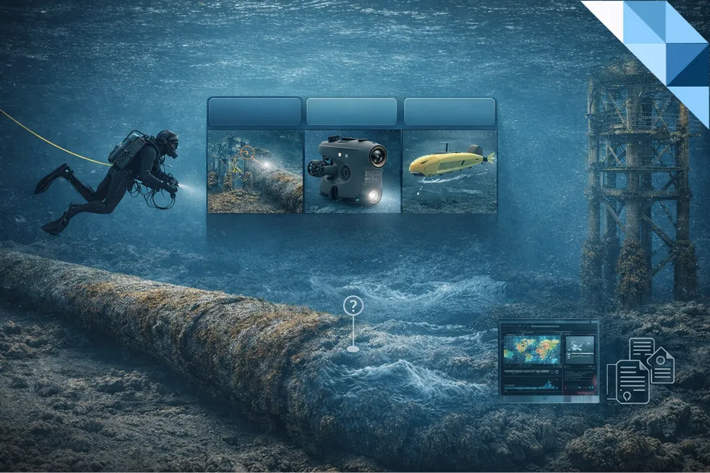
Platform Selection: Diver vs ROV vs AUV (Engineering Comparison)
Diver inspection
Strengths
- direct close access and tactile control
- flexible close visual work in confined geometry
- effective for localized tasks when conditions are safe and controlled
Limitations
- higher personnel exposure and operational constraints
- limited endurance and weather windows
- less scalable for large-area coverage
Best fit
- shallow, controlled sites with good safety conditions
- localized close inspection where human dexterity is required
ROV inspection (the scalable evidence platform)
Strengths
- strong safety profile compared to diver exposure
- scalable coverage, repeatable routes, and structured evidence
- effective in limited visibility when sonar is integrated
- supports selected measurements (UT/CP) when planned properly
Limitations
- scope must match class capability and tooling limits
- station-keeping and access can be challenged by current and geometry
- heavy intervention is not achievable without work-class systems
Capability clarity
NWE underwater inspection capability is based on ROV Class I and Class IIA systems and is not work-class. Inspection scopes should be engineered accordingly.
A practical foundation for evidence design in turbidity:
Low-Visibility Playbook: Multibeam & Imaging Sonar as Coverage Evidence
https://nwegroup.no/low-visibility-sonar-coverage-proof/
AUV inspection (high-efficiency screening and mapping)
Strengths
- fast large-area coverage (corridor mapping, route surveys)
- repeatable survey patterns and strong coverage efficiency
- excellent for baseline screening and anomaly detection for follow-up
Limitations
- limited ability to perform close visual confirmation
- limited ability to take contact measurements (UT/CP)
- most effective when paired with follow-up verification (often ROV)
Best fit
- wide-area screening: pipelines, long corridors, seabed interaction mapping
- campaigns where you want to find “where to look closer” first, then deploy ROV for confirmation and measurements
A practical AUV→ROV workflow example is reflected in:
Underwater Pipeline Inspection: Free-Spans, Exposure & AUV→ROV NDT
https://nwegroup.no/underwater-pipeline-inspection-free-spans-exposure-auv-rov-ndt/
Decision Matrix: Choosing Diver vs ROV vs AUV
Use this matrix as a starting point, then refine by asset type and site constraints.
1) Visibility and turbidity
- Good visibility: diver or ROV can deliver strong visual evidence
- Low visibility: ROV with sonar evidence becomes the defensible option
- Extreme turbidity: sonar-led inspection may be required; plan limitations explicitly
Recommended reading for turbidity evidence planning:
https://nwegroup.no/low-visibility-sonar-coverage-proof/
2) Coverage size and speed requirements
- Small/localized scope: diver or ROV
- Large-area corridor mapping: AUV first, then ROV for confirmation
- Large complex assets: ROV routes with zone-based evidence discipline
3) Safety and operational risk
- Elevated risk environment (cold water, contamination, access constraints): prioritize ROV
- Controlled shallow site: diver can be feasible if risk controls allow
4) Measurement needs (UT/CP)
- If the decision needs numbers: use ROV measurement tooling where repeatable, or plan alternative approaches
- If screening is sufficient: AUV/ROV visual + sonar may be enough
5) Required inspection depth (GVI vs CVI vs DVI)
- DVI demands stable station-keeping and close access: diver or ROV depending on safety and access
- CVI is often optimal with ROV for coverage + confirmation
- GVI can be delivered efficiently by AUV or ROV depending on asset
Evidence Engineering: How to Plan an Inspection That Reviewers Accept
Define an inspection zone model
Divide the asset into zones that can be inspected, referenced, and re-checked:
- zones tied to drawings, known features, or chainage (for pipelines)
- consistent naming conventions across campaigns
Build a coverage plan with proof logic
- route plan and pass logic (what is covered in what order)
- time-coded media indexing tied to zones
In low visibility, include sonar-based coverage evidence:
https://nwegroup.no/low-visibility-sonar-coverage-proof/
Define limitation statements before mobilization
Write what will reduce confidence:
- visibility thresholds
- marine growth masking
- access limits
- station-keeping limits in current
Limitations are acceptable to reviewers; over-claiming is not.
Deliverables: What an Audit-Ready Package Looks Like
A professional underwater inspection deliverables pack typically includes:
1) Scope, method, and constraints summary
- platform used (diver/ROV/AUV/hybrid)
- environmental constraints (visibility/current)
- cleaning policy (if any)
- measurement scope (if any)
2) Coverage evidence
- zone plan and route map
- coverage statement with limitations
- time-coded media index mapped to zones
3) Findings register (decision-ready)
Each finding includes:
- unique ID
- location reference (zone/feature/chainage)
- severity category
- evidence reference (timecode/media)
- recommended next action (monitor/escalate/repair)
4) Measurement package (when included)
- UT/CP tables tied to location IDs
- verification/calibration evidence retained with the dataset
- repeatability controls (defined re-check subset)
For practical guidance on measurement evidence quality:
https://nwegroup.no/rov-ndt-ut-cp-best-practice/
5) Technical conclusion and integrity recommendation
- what the evidence supports and what it does not
- escalation triggers and recommended follow-ups
- basis for any interval recommendation (when relevant)
Underwater Inspection in Practice: Typical Workflows
Workflow A — ROV-first (most common for complex assets)
- Sonar-assisted navigation and coverage proof
- Visual screening (GVI) and close confirmation (CVI) at hotspots
- Targeted measurements (UT/CP) where they change decisions
- Findings register + decision memo
Workflow B — AUV screening → ROV confirmation (efficient for corridors)
- AUV identifies spans, exposure, anomalies, corridor changes
- ROV confirms anomalies with close visual and measurements where needed
- Deliverables packaged for integrity decisions
Reference workflow example:
https://nwegroup.no/underwater-pipeline-inspection-free-spans-exposure-auv-rov-ndt/
When 3D Evidence Is Worth It (Photogrammetry and Digital Twins)
If acceptance depends on geometry (deformation, denting, interface fit) or you need repeatable dimensional evidence, photogrammetry can deliver a structured dataset.
Subsea Photogrammetry & Digital Twins: Scale Control, Pass Design, Uncertainty & Class Acceptance
https://nwegroup.no/subsea-photogrammetry-digital-twin/
Use Cases Where Underwater Inspection Prevents Downtime
No-drain inspections for utilities and intakes
When draining or shutdown is costly, ROV inspection can keep assets online:
Utilities, Dams & Intakes: Keep Assets Online with No-Drain ROV Inspections
https://nwegroup.no/utilities-dams-intakes-keep-assets-online-with-no-drain-rov-inspections/
Evidence-driven pipeline diagnostics
A project-style example showing how subsea evidence supports decisions:
NWE Subsea Inspection of 24-Inch River-Crossing Pipeline
https://nwegroup.no/nwe-subsea-pipeline-inspection/
FAQs
When should I choose AUV over ROV?
Choose AUV for large-area screening and mapping (corridor surveys, baseline screening) when close visual confirmation and contact measurements are not the primary requirement. Plan ROV follow-up for verification and measurements.
How do you defend coverage in poor visibility?
Design the inspection to include sonar-based coverage proof and explicit limitation statements. This keeps coverage claims defensible even when optical evidence is constrained:
https://nwegroup.no/low-visibility-sonar-coverage-proof/
When should underwater inspection include UT thickness and CP surveys?
Include UT/CP when the integrity decision requires numbers: wall-loss trending, protection performance confirmation, or anomaly verification. Ensure repeatability, traceability, and calibration evidence are built into the deliverable pack:
https://nwegroup.no/rov-ndt-ut-cp-best-practice/
How does ISO 19901-9 relate to underwater inspection deliverables?
ISO 19901-9 is an ISO-family SIM governance reference. Underwater inspection deliverables support SIM by providing traceable evidence, structured findings, and repeatable datasets that feed lifecycle integrity decisions.
