


ROV-based underwater inspection is most successful when scope, tooling, and evidence requirements are aligned from the start. The goal is not “collecting video.” The goal is producing decision-grade, reviewable evidence for integrity management—while reducing risk to personnel and minimizing operational disruption.
This article explains how ROV inspection is typically engineered: what ROV Class I and Class IIA systems can realistically deliver (and what they cannot), how sensor payloads are selected, which tooling is credible, how HSE and operational risks are managed, and what an audit-ready deliverables pack should look like.
Capability clarity matters: NWE’s underwater inspection capability is based on ROV Class I and Class IIA systems and is not work-class ROV. Scope should be planned accordingly.
Key Outcomes an ROV Inspection Must Deliver
A professional ROV inspection should answer specific integrity questions, such as:
- What was inspected and what was not (coverage proof)?
- What is the observed condition (coating breakdown, damage, anomalies)?
- Where exactly are findings located (traceable IDs and mapping)?
- What evidence supports the conclusion (time-coded media, measurement records where applicable)?
- What should happen next (repair/monitor/escalate/special inspection)?
Evidence packaging should be structured for third-party review (a NORSOK U-102 style “reviewability” mindset): clear scope, consistent IDs, time-coded evidence, and documented constraints.
ROV Classes for Inspection: What Class I and Class IIA Mean in Practice
Class I ROV (Observation / Light Inspection)
Typical strengths
- high-quality visual surveys (GVI/CVI where feasible)
- tight access in confined areas
- efficient screening and condition confirmation
- low-mobility environments (when currents allow station keeping)
Typical constraints
- limited payload, limited power for heavy tooling
- manipulation capability (if any) is light-duty and scope-dependent
- measurement tasks require careful planning and stability
Class IIA ROV (Inspection / Light Work, Not Work-Class)
Typical strengths
- improved station keeping and payload compared with Class I
- more credible integration of sonar payloads and measurement tooling within limits
- stronger evidence reliability under moderate constraints
Typical constraints
- still not a substitute for work-class intervention
- heavy intervention tasks (cutting, complex valve operations, large force manipulation) are outside the normal envelope
Why “Not Work-Class” Must Be Stated
Work-class ROVs are designed for heavy intervention (high-power hydraulics, stronger manipulators, large tooling suites). A Class I/I IIA inspection capability is excellent for inspection evidence and selected measurements—provided the method statement and deliverables match what the system can actually execute.
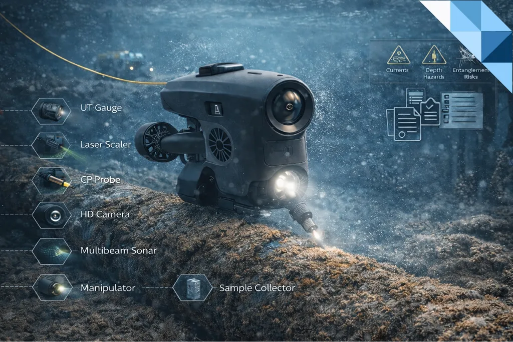
Sensor Payload Engineering: Choosing the Right Evidence Stack
1) Optical Video (Primary Evidence Layer)
Use for
- coating condition, marine growth coverage, impact damage
- weld seams, attachments, interfaces (when visibility and proximity allow)
Engineering controls
- stable pass planning (consistent standoff, controlled speed)
- orthogonal views at critical details
- time-coded recording for review and traceability
2) Imaging Sonar / Multibeam (Coverage Proof + Navigation in Turbidity)
In low visibility, sonar often becomes the backbone of “what was covered” and “where we were.”
Use for
- coverage proof when optics cannot defend it
- structural geometry confirmation
- navigation around complex assets
For practical, field-oriented coverage-proof logic in turbidity, see:
Low-Visibility Playbook: Multibeam & Imaging Sonar as Coverage Evidence
3) Positioning and Referencing (Where Evidence Gains Credibility)
ROV evidence becomes decision-grade when it can be tied to a location model.
Common approaches include:
- relative referencing to known asset features
- structured zone mapping (asset divided into reviewable zones)
- consistent naming and IDs across campaigns
4) Photogrammetry / 3D Reconstruction (When Dimensional Confidence Is Required)
When acceptance depends on geometry or dimensional confirmation (deformation, denting, geometry change, interface fit), photogrammetry can produce a reviewable 3D dataset.
See:
Subsea Photogrammetry & Digital Twins: Scale Control, Pass Design, Uncertainty & Class Acceptance
5) Measurement Payloads (When Numbers Are Needed)
ROV inspection can include selected measurements (scope-dependent), such as:
- UT thickness measurements (where credible and repeatable)
- CP surveys (where protection performance must be demonstrated)
For measurement discipline that remains repeatable and reviewer-friendly, see:
ROV-Deployed NDT in Practice: UT & CP That Deliver Repeatable, Class-Ready Results
Tooling and What’s Realistic with Class I / Class IIA (Inspection-Focused)
Typical inspection tooling (credible within limits)
- cleaning tools for localized visibility improvement (scope-dependent)
- scale references / laser scaling (for size confirmation where feasible)
- sonar payloads for coverage proof
- light manipulators (if fitted) for camera orientation and simple interactions
Tooling that requires special planning (often outside normal inspection envelope)
- heavy mechanical intervention
- high-force operations or complex manipulations
- tooling that requires stable contact under strong currents
- extensive cleaning campaigns intended to “replace” dry access
Engineering rule: if the decision requires heavy intervention, plan the right platform and method—do not force-fit it into an inspection ROV campaign.
Inspection Methods Delivered by ROV: What You Can Defend
General Visual Inspection (GVI)
Best for broad screening and coverage confirmation.
Close Visual Inspection (CVI)
Used at:
- critical interfaces and attachments
- known hotspots from history
- areas flagged by owner/Class/Flag
- anomalies found during GVI that require confirmation
Detailed Visual Inspection (DVI)
Used for decision-grade evidence on:
- damage characterization
- specific acceptance/engineering disposition needs
- confirmation tasks where confidence must be high
Evidence Quality and Deliverables: What Makes an ROV Inspection “Audit-Ready”
An audit-ready deliverables pack typically includes:
1) Scope and Coverage Proof
- zone plan and route logic
- coverage statement with limitations clearly stated
- time-coded media index mapped to zones/IDs
2) Location Model and Traceability
- stable IDs tied to drawings/asset register
- consistent naming conventions across campaigns
3) Findings Register (Decision-Ready)
Each finding should have:
- unique ID
- location reference (zone/ID)
- severity category
- evidence reference (timecode/media)
- recommendation (monitor/escalate/repair)
4) Measurement Pack (When Included)
- UT/CP tables tied to location IDs
- verification/calibration evidence retained with the dataset
- repeatability controls (defined re-check subset)
This evidence-first structure supports efficient third-party review and reduces rework.
HSE and Operational Risk Controls for ROV Inspection
Why ROV Is Often the Safer Inspection Option
ROV inspection reduces diver exposure and can reduce risk in:
- cold water operations
- constrained access zones
- contaminated water environments
- high-current or hazardous areas (within operational limits)
Key operational hazards to engineer out
- entanglement (lines, nets, protrusions)
- collision risk (asset contact, thrusters near sensitive surfaces)
- loss of station keeping in current/turbidity
- dropped equipment risk (tooling discipline)
- vessel operations interface risk (launch/recovery, deck safety, lifts)
Controls that protect safety and evidence quality
- pre-dive risk assessment and SIMOPS planning
- defined abort criteria (visibility/current thresholds)
- controlled passes and speed limits near sensitive structures
- clear comms and roles (pilot, data recorder, inspection lead)
Standards and Governance: Keep ISO with ISO, API with API
ROV inspection deliverables commonly feed integrity programs governed by different standards families. Documentation must remain consistent within the selected family:
ISO family (international)
- Design references may include ISO 19901 series and ISO 19902 (asset dependent)
- SIM governance: ISO 19901-9
API family (American)
- Design references: API RP 2A-WSD / API RP 2A-LRFD
- SIM governance: API RP 2SIM
ROV inspection outputs should be structured so they can be consumed by the chosen integrity governance model without mixing clause systems.
If your integrity program is RBI-driven, these reads support the decision logic layer:
- Risk-Based Inspection vs Time-Based Inspection: Methodology Guide
- RBI Data Requirements (API 580/581): Build a Model You Can Defend
Practical Use Cases Where Class I / Class IIA ROV Inspection Excels
Pipelines and river crossings (screening + targeted follow-up)
For a field-oriented example of subsea pipeline inspection logic (including follow-up with ROV/NDT where needed), see:
Underwater Pipeline Inspection: Free-Spans, Exposure & AUV→ROV NDT
Utilities, dams, and intakes (inspection without draining)
ROV inspection is often ideal where draining is costly or impractical:
Utilities, Dams & Intakes: Keep Assets Online with No-Drain ROV Inspections
Evidence-driven project delivery example
NWE Subsea Inspection of 24-Inch River-Crossing Pipeline
FAQs
What is the main difference between Class I and Class IIA ROV for inspection planning?
Class IIA generally supports higher payload and better control, which improves evidence reliability and broadens the feasible sensor/tool set. Both remain inspection-focused and are not substitutes for work-class intervention.
How do you defend coverage in poor visibility?
Plan for turbidity and include sonar-based coverage evidence so coverage claims remain defensible:
Low-Visibility Playbook: Multibeam & Imaging Sonar as Coverage Evidence
When should an ROV inspection include UT/CP measurements?
When the integrity decision requires numbers (trending wall loss, confirming protection performance) and the measurement can be executed repeatably with traceability. Practical controls are covered here:
ROV-Deployed NDT in Practice: UT & CP That Deliver Repeatable, Class-Ready Results
How does ISO 19901-9 relate to ROV inspection deliverables?
ISO 19901-9 is an ISO-family SIM governance reference. ROV inspection deliverables support SIM by providing traceable evidence, findings registers, and repeatable datasets that feed lifecycle integrity decisions.

One Response
Very good i like it