


Underwater inspection starts with what you can see—then decisions are made with what you can measure. For subsea assets, NDT is the bridge between observation and engineering action: remaining wall thickness, protection performance, and the internal condition of hollow members.
This article focuses on the underwater NDT methods most commonly used to support subsea integrity decisions:
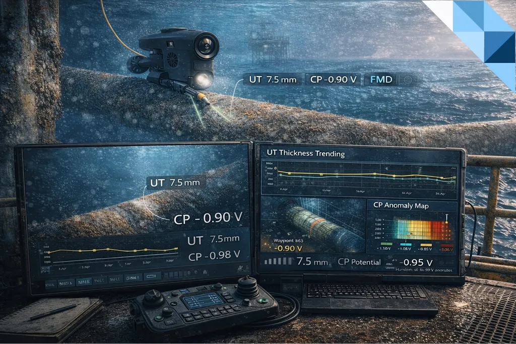
- UT thickness for wall-loss measurement and trending
- CP surveys for cathodic protection performance and anomaly detection
- Flooded Member Detection (FMD) for screening hollow members
It also explains what “acceptance” means in a practical offshore context: not just method capability, but evidence quality, repeatability, and traceability that stand up to owner and third-party review.
Underwater NDT in Offshore Integrity Programs
Underwater NDT is rarely performed “because it’s available.” It is performed because it answers questions that drive action:
- How much metal is left—and is it thinning faster than expected? (UT)
- Is cathodic protection performing, and where are anomalies developing? (CP)
- Are hollow members potentially flooded, and what follow-up is required? (FMD)
The strongest subsea integrity programs don’t overload the scope with measurements. They collect only the measurements that reduce uncertainty enough to justify the next decision (repair, monitor, re-inspect sooner, or extend intervals).
If you want a practical, field-based view of how to collect subsea measurements that remain repeatable and reviewer-friendly, read:
ROV-Deployed NDT in Practice: UT & CP That Deliver Repeatable, Class-Ready Results
Choosing the Right Method: Mechanism → Evidence
A robust selection rule is simple: match the method to the dominant damage mechanism and the decision you need to support.
Quick selection guide
- External corrosion / wall loss → UT thickness + CP context
- Protection performance → CP mapping + targeted verification
- Hollow member flooding risk (structures) → FMD screening + defined follow-up actions
- Crack/fatigue concerns → typically require dedicated crack-focused methods and planning (method depends on material, access, coating, and acceptance criteria)
This article focuses on UT/CP/FMD because they form the core measurable evidence loop in many subsea inspection campaigns.
UT Thickness Underwater: Wall Loss Measurement and Trending
What UT Thickness Is Used For
UT thickness is used to:
- quantify remaining wall thickness,
- identify localized thinning hot-spots,
- establish thinning rates (trending),
- support integrity decisions (monitoring vs intervention).
UT becomes significantly more valuable when you can trend the same points over time under controlled conditions.
Where Underwater UT Works Best
Underwater UT performs best when:
- the measurement location is stable and clearly identifiable,
- probe coupling is controlled,
- surface condition is understood (marine growth/coating effects are considered),
- calibration and verification records are retained and linked to the dataset.
Key Limitations Offshore
UT results can become unreliable when:
- access is unstable (currents, poor station keeping, awkward geometry),
- surface condition varies between campaigns (growth removal differences, rough coatings),
- repeatability is not engineered (points cannot be revisited consistently),
- verification evidence is missing (calibration/verification cannot be demonstrated later).
These limitations don’t mean UT “doesn’t work”—they mean UT must be executed with a discipline that protects repeatability.
UT Deliverables That Reviewers Accept
A UT deliverable set that supports audit and technical review typically includes:
- UT table (location ID, timestamp, thickness, method remarks),
- clear location model (drawing tie-in, member/node reference),
- calibration/verification evidence retained with the dataset,
- repeatability checks (defined re-check subset),
- short interpretation note explaining any anomalies and confidence.
For exactly how to package UT (and CP) so it remains class-ready, use:
ROV-Deployed NDT in Practice: UT & CP That Deliver Repeatable, Class-Ready Results
CP Surveys Underwater: Proving Protection Performance
What a CP Survey Must Demonstrate
A CP survey exists to prove whether cathodic protection is performing and to identify:
- current starvation zones,
- coating breakdown patterns,
- abnormal gradients that require verification and action.
A CP survey becomes decision-grade when it doesn’t just report numbers, but connects:
- where the anomaly is,
- how it was measured,
- and what follow-up is recommended.
CP Survey Approaches Used Offshore
Most CP programs combine two layers of evidence:
1) Coverage evidence (pattern mapping)
Used to understand the distribution of potentials and identify hot-spots.
2) Targeted verification
Used where mapping indicates anomalies or where decisions require higher confidence.
CP Deliverables That Stand Up in Review
A reviewer-friendly CP package typically includes:
- CP dataset tied to location IDs,
- timestamps and measurement approach description,
- anomaly register with recommended follow-up actions,
- comparison narrative: what changed vs previous campaigns and why.
For a practical “how-to” on making CP outputs repeatable and accepted, see:
ROV-Deployed NDT in Practice: UT & CP That Deliver Repeatable, Class-Ready Results
Flooded Member Detection (FMD): Screening Hollow Members
What FMD Is Used For
FMD is used as a screening method to detect suspected flooding in hollow structural members (where applicable to the asset type). It supports:
- prioritization (which members deserve focused follow-up),
- planning (where to allocate close visual and engineering review),
- integrity decisions (when flooding changes structural capacity assumptions).
How to Treat FMD Results in Integrity Decisions
FMD is best treated as a trigger rather than a final conclusion. A credible workflow is:
- FMD screening identifies a suspected flooded member
- Follow-up inspection confirms context (focused close visual where relevant)
- Engineering review considers implications and defines next actions
- The member is tracked in a register until closure
FMD Deliverables That Support Review
A defensible FMD output typically includes:
- member ID and location reference,
- screening result with confidence statement,
- recommended follow-up actions,
- register-based tracking across campaigns.
Reporting and Acceptance: What Makes Underwater NDT “Audit-Ready”
Underwater NDT is accepted faster when reviewers can reproduce the logic from evidence. A practical audit-ready deliverable bundle includes:
- Scope and coverage statement (what, where, how much)
- Location ID model tied to drawings/asset register
- Time-coded media index (supporting evidence for work performed)
- Measurement tables (UT/CP/FMD) linked to IDs and timestamps
- Calibration/verification records stored with the dataset
- Findings list + exception register (severity, owner, due date, closure evidence)
- Technical sign-off showing review and approval steps
In low-visibility campaigns, evidence quality often depends on sonar-assisted coverage proof. For an approach focused on reviewable coverage evidence, see:
Low-Visibility Playbook: Multibeam & Imaging Sonar as Coverage Evidence
ROV Deployment Notes: Capability and Planning Clarity
ROV-based inspection is often the safest way to collect underwater evidence at scale. For planning accuracy, inspection scopes should match the platform’s capabilities and tooling limits.
(When your broader underwater program includes pipeline screening, spans/exposure checks, and targeted follow-up, this related read is useful for method selection context:)
Underwater Pipeline Inspection: Free-Spans, Exposure & AUV→ROV NDT
Frequently Asked Questions
How do I make UT trending defensible across campaigns?
Use stable location IDs, repeatable measurement procedures, documented calibration/verification, and a defined repeatability re-check subset. Without repeatability controls, trend slopes become weak evidence.
Should CP surveys be mapping-only or include verification?
Mapping is valuable for pattern insight, but anomalies typically require targeted verification to support intervention decisions. The strongest CP reporting connects patterns to confirmed values and recommended actions.
Is FMD a final confirmation of flooding?
Treat FMD as a screening tool that triggers follow-up inspection and engineering assessment where required. Its value is in prioritization and traceable decision workflow, supported by member IDs and register-based tracking.
What about crack detection methods underwater?
Crack-focused inspection typically requires dedicated planning and method statements based on material, access, coating condition, and acceptance criteria. When crack risk is credible, include it explicitly in scope and reporting governance rather than assuming it is covered by general measurements.
