


Low-Visibility Playbook: Multibeam & Imaging Sonar as Coverage Evidence
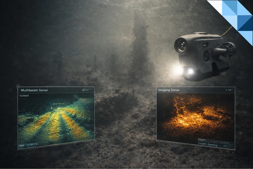
In low-visibility underwater inspections, sonar-based evidence—using imaging sonar and multibeam—becomes the primary way to prove coverage and access, not to replace visual confirmation. When turbidity, backscatter, or night operations limit optics, sonar delivers auditable plan views, lane mosaics, and georeferenced tracks that show exactly where the ROV went and what was covered.
Sonar findings are then tagged and revisited with optical CVI (and UT where required) to close the loop for acceptance and decision-making.
Why Sonar Matters When Optical Evidence Fails
High turbidity, suspended sediment, aeration, or poor lighting can quickly degrade optical footage. In these conditions, relying on video alone makes coverage unverifiable and invites rework.
Imaging sonar and multibeam solve this by providing:
- Lane-based coverage proof
- Georeferenced mosaics tied to UTC time
- Repeatable evidence independent of water clarity
Sonar does not replace CVI—it protects it by proving that inspection coverage was achieved even when optics are degraded.
For inspection levels and deliverables context, see Fixed Offshore Structures: Underwater Inspection Requirements under ISO 19902 (2020).
For ROV platform envelopes, station-keeping, and payload choices, align scope and deliverables with Underwater Inspection (ROV) under Inspection Services.
Where sonar is used to support in-water acceptance instead of dry-dock or yard access, keep the evidence chain explicit (coverage proof → tagged revisits → acceptance-grade dossier) as it is typically executed in Underwater Inspection (ROV) campaigns.
When Optical Fails, Sonar Defines the Envelope
Different sonar tools serve different inspection needs:
- Imaging sonar
Best for near-field visualization around:
- braces and stiffeners
- sea chests and gratings
- complex geometry and cluttered structures
- Multibeam sonar
Best for area coverage and mosaics across:
- hulls and quay walls
- pipelines, berths, and outfalls
- harbor floors and approach corridors
Always publish:
- effective range,
- beam width and sector settings,
- capture profile limits (e.g. high flow, heavy aeration).
In mixed inspections, a short optical clip at lane start and end improves traceability and reviewer confidence.
Mission & Track Design: Where Coverage Proof Starts
Coverage proof begins before the ROV is launched.
Define and document:
- Lane spacing and overlap sufficient for mosaicking
(typically 20–40%, depending on altitude and beam width) - Speed and altitude bands
- slower/lower for fine structures
- higher for broad area sweeps
- Navigation aids
- DVL/INS as baseline
- USBL/RTK where available
- Time-sync source
- GPS → NTP → vehicle
- Control segments
- short repeated passes to quantify drift and repeatability
Publish the plan as a simple grid with lane IDs.
During execution, log lane start/stop times with UTC.
Mosaics & Quality Control (QC): Making Sonar Auditable
A sonar mosaic is only useful if its quality is transparent.
Core QC Elements
- Drift control
Insert cross-lanes or fiducial turns to bound cumulative navigation error. Shorten lanes if INS confidence degrades. - Artifact handling
Identify and mask multipath streaks, shadow zones, and edge shimmering. Document filters used. - Stitching tolerance
Report residuals at overlaps (e.g. mean offset ± SD). Include scale bars and color legends. - Confidence map
Provide a grayscale or alpha layer indicating confidence per pixel to prevent over-interpretation of weak returns.
Include a compact QC table:
- overlap %
- residuals
- masked area %
- time-sync variance
This table often decides first-pass acceptance.
Tagging Sonar Hits → CVI / UT Revisits
Sonar identifies candidates. CVI confirms them.
For each sonar hit, tag:
- Lane ID + UTC timestamp + vehicle pose
- Hit class
(geometry change, debris, scour pocket, coating anomaly, rack blockage) - Revisit method
- optical CVI
- UT (only if a measurement decision is required)
- Priority (monitor / mitigate / repair)
- Breadcrumb evidence
- sonar screenshot with cursor box
- short clip showing the detection
When visibility allows, execute a short optical confirmation pass at the same waypoint.
If the item implies measurement or acceptance logic, cross-link to ROV-Deployed NDT in Practice: UT & CP That Deliver Repeatable, Class-Ready Results and (for method fundamentals) What Is NDT? A Complete Guide to Techniques & Benefits.
Building a Class-Ready Sonar Dossier
Acceptance depends on how easily a reviewer can trace evidence.
Recommended Dossier Contents
- Overview map
Lane polylines, direction arrows, covered vs pending shading. - Lane table
Lane ID, UTC start/stop, distance, average speed/altitude, overlap score. - Hit register
Mapping each candidate to lane/time, class, priority, and revisit outcome. - Media set
Georeferenced mosaics, lane clips, paired optical CVI (and UT where applicable). - Time-sync proof
Offset logs and synchronization notes showing alignment across sonar and video.
Make it impossible to ask: “Where exactly was this inspected?”
Common Pitfalls & Acceptance Thresholds
Why Sonar Evidence Gets Rejected
- No overlap or weak navigation → unverifiable mosaics
- Unsynced clocks between sonar and cameras
- No revisit tagging → “interesting” but operationally useless data
- Over-smoothed mosaics hiding features or creating false edges
Acceptance improves dramatically when you publish overlap %, residuals, masked area %, and UTC logs alongside the mosaic—and link any decision-driving hit to CVI or UT follow-up.
Practical Capture Rules That Keep Sonar Honest
- Stabilize altitude; avoid sudden heave.
- Fly constant-speed lanes; pause only at planned fiducials.
- Keep transducer faces clean; recheck alignment after contact.
- In high flow, shorten lanes and increase overlap.
- Add cross-lanes around piles, braces, and strong shadow zones.
Coverage Proof Checklist (Quick Reference)
| Item | What to Record | Why It Matters |
|---|---|---|
| Lane design | Lane IDs, spacing, overlap targets | Enables mosaic QC and gap detection |
| Navigation | DVL/INS mode, USBL/GPS quality | Controls georeferencing drift |
| Time-sync | UTC source, offset logs | Links sonar to CVI/UT revisits |
| Mosaic QC | Overlap residuals, masked area %, artifacts log | Lets reviewers judge confidence |
| Hit tagging | Lane ID + UTC + class + priority | Converts data into actions |
| Revisit outcome | CVI/UT reference + decision | Closes the acceptance loop |
FAQs — Acceptance & Evidence
Can sonar alone be accepted as inspection evidence?
Yes—for coverage proof. Use mosaics with documented overlap, QC metrics, and UTC-synced logs. Decisions require paired CVI or UT.
What lane overlap should I target?
Typically 20–40%, tuned to altitude, beam width, flow, and geometry complexity.
How do I synchronize timestamps across sonar and cameras?
Use a single UTC source (GPS → NTP → vehicle), verify offsets at start and end, and store the sync log in the dossier.
What breaks sonar mosaics most often?
Navigation drift, inconsistent speed/altitude, and unreported artifacts. Cross-lanes and overlap residuals bound error.
How do I link sonar hits to CVI or UT?
Tag each hit with lane/time/pose, create a waypoint, and capture a short optical or UT confirmation. Store both as one anomaly record.
Turn Turbidity into Proof
We design sonar-led low-visibility inspections with clean coverage plans, revisit tagging, and time-synced media—so surveyors see evidence, not excuses.
